

The pressure vessel systems that are interconnected by piping are widely used in petrochemical and process plants. If not accurately designed, buckling or leaking at the vessel shell or head can occur.
In this article, Paulin Research Group's very own Dr. Delin Wang, Ph.D--Senior FEA Analyst and Developer--breaks down how determining allowable nozzle loads can help engineers design for better pipe stress compliance.
Common Design Problems Engineers Face with Modern Piping Systems
During the build of these systems, designers often face two common problems:
-
The mechanical loads exerted on the vessels like sustained and thermal loads are not known to the vessel designers when the vessels are ordered. The only known load may be the internal pressure that the vessels are subject to.
-
Piping engineers responsible for determining pipe layout and support arrangements as well as calculating the mechanical reactions on the vessels exerted by the piping system do not know the allowable loads on the vessels, which can affect the designer’s ability to optimize the piping layout and support arrangements to minimize piping loads. If these loads are over the limit, the nozzle-vessel intersection can become overstressed or overloading can happen to the nozzle-piping flange connection [1].
So, assessing the maximum allowable nozzle loads can help with two things:
-
To provide vessel designers with nozzle loads so that they can design the vessel shell or head that’s attached to the nozzle prior to the design of the piping systems.
-
To provide piping designers with guidelines for piping designs that terminate at a vessel nozzle to avoid the overstress of the vessel shell or head [2].
Why Determining Maximum Allowable Nozzle loads Is Hard
Calculating nozzle loads for the pressure vessel before the exact piping layout and support arrangements are known can result in design problems. The vessel designer cannot treat this problem only in a mathematical or theoretical sense.
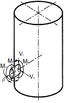
In fact, a purely theoretical or mathematical treatment that includes all loads equally delivers results that are usually unnecessary in practice. For example, in the figure below, there are three forces and moments exerted by the piping system on the vessel terminal flange.
Figure 1: Moments and Forces on Flanged Connections
Common engineering practices show that the Mc moment aligned with the circumferential direction can cause more potential damage to the vessel than the other two moments since the vessel is stiffer along the circumferential direction. The radial force P, which tends to open or separate the flange, can cause a leakage hazard. Therefore, these loads should be kept low in magnitude in comparison to other loads.
In choosing the maximum allowable nozzle loads, the combination of these forces and moments typically produces stress less than the maximum allowable stress in the vessel. However, there could be an infinite number of load combinations that a designer can choose.
So, developing a method that can assess the optimal set of nozzle loads prior to beginning a design can be difficult to do. If the loads are too low, the piping design may become expensive. If the loads are too high, unnecessary reinforcement is required for the vessel nozzle design and can result in increased production or material costs [3,4].

How to Determine Maximum Allowable Nozzle Loads
As mentioned above, determining allowable loads can be complicated because an infinite range of load combinations is possible. Maximum individual loads can be calculated for the situation where all other loads are zero. Certain combinations of loads can also be assumed.
The table below shows a typical load report that lists conservative combinations of loads that are “realistic” combinations of loads.
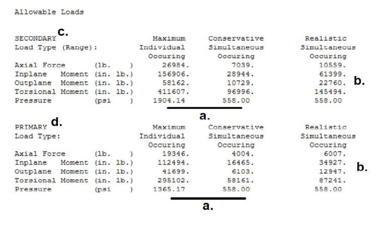
Figure 2: Allowable Load Table
In generating the Allowable Load Table, the following procedures were adopted:
- A maximum pressure can be calculated when all other loads are zero. A lower design pressure is used to compute the allowable external loads.
- Realistic allowable loads can be based on combination theories that are more accurate than SRSS (Square Root of the Sum of the Squares) methods.
- Secondary and primary loads are calculated differently because the allowable stresses are different.
Additionally, maximum individual loads can be calculated for the situation where all other loads are zero and certain combinations of loads can be assumed.

Determining Maximum Loads with Pipe Stress
Further, allowable nozzle loads can be calculated when the vessels are designed or when pipe stress is performed. In both cases, the loads applied to the nozzles by the attached piping must be limited by the calculated allowable nozzle loads.
Difficulties can occur for the pipe designer when vessel designs are optimized for pressure or little additional thickness is available in the vessel wall for extra external loads. When the design pressure is close to the maximum allowable pressure, the allowable loads get smaller and can go to zero.
The report below shows that for the vessel analyzed the allowable in-plane moment drops from 148,480 in.lb. to 0 in.lb. when the pressure increases from 8000 psi to 8750 psi (or per square inch).
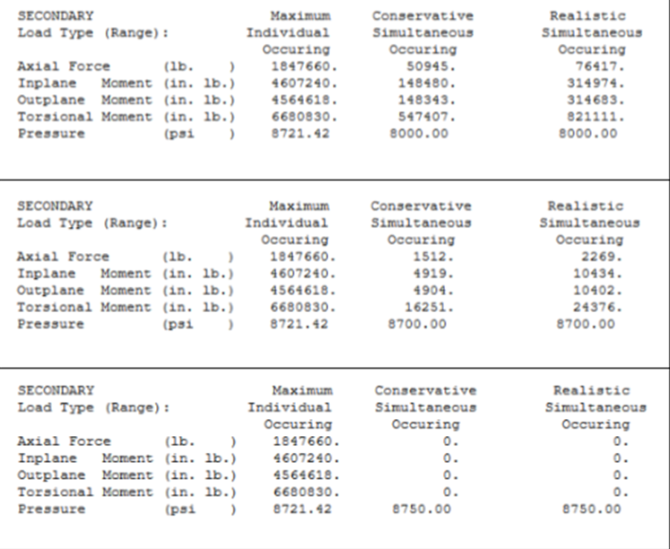
Figure 3: Stress Report for Vessel A
Most allowable loads are based on superposition and the linear elastic calculation of displacements and stresses. When internal pressure is increased, the external load capacity can increase, which the designer generally knows intuitively. The external load increase due to pressure is not reflected in linear elastic solutions.
Pressure stresses and external load stresses do not linearly add up when ovalization (large rotation) controls the stress interaction. However, nonlinear analysis using elastic-plastic theory with large rotation can solve this problem.
Displacements can be computed due to the application of the allowable external loads and compared to nozzle fabrication tolerances. The report below shows a series of these displacement calculations. As long as these displacements are less than 1% of the diameter of the vessel, the allowable loads are generally reasonable.
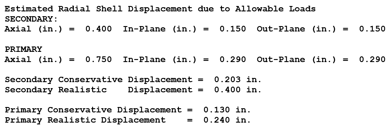
Figure 4: Displacement Calculations
Using WRC 107/297 and 537 to Analyze Nozzle Stresses
The methods proposed in the Welding Research Council or WRC 107/297/537 bulletins are well-accepted methods in the industry for analyzing stresses due to external loads in cylindrical and spherical shells. The following is a schematic illustration of one method about computing allowable loads:
Step 1: Compute stress factors for each load:
Sax = SCFax x Fax / A
Sin = SCFin x Min / Z
Sout = SCFout x Mout / Z
Stor = SCFtor x Mtor / Z
Spre = SCFpre x PD/4T
Step 2: Compute allowable loads:
(3 (M/Z)2 + (PdesD/4T)2 )0.5 = Sall
Maxallow = M / SCFax
Minallow = M / SCFin
Moutallow = M / SCFout
Pallow = Sall x 4T/D / SCFpre
WRC Calculators Can Determine Piping and Nozzle Stress
Determining allowable nozzle loads is important to consider in the design of pressure vessel systems that are widely used in petrochemical and process plants today because it helps prevent the piping structures from buckling or leaking at the vessel shell or head.
WRC bulletins provide calculation methods to help designers better analyze stresses due to external loads. Additionally, design and analysis software that exist today include built-in WRC calculators like FE107 that aid in this process, and further, help the designer model pad, unreinforced, and hillside models for stress compliance with FEA capabilities.
It's pretty simple:
- Input your design values into the calculator,
- Click
- and FE107 validates the WRC calculation against FEA models.

FE107 is part of both the NozzlePRO and FEPipe software modules. If you’re looking for a WRC calculator that can determine FEA as well, request a consult today and see how our FEA capabilities help expedite your safe and compliant pressure vessel designs.
Appendix
References
[1] W. J. Stikvoort, Proper interface design for pressure vessels, Chemical Engineering, 101(6) (1994) 133-134.
[2] D. R. Moss, M. Basic, Pressure Vessel Design Manual (4th edition), Elsevier Butterworth Heinemann, 2013.
[3] C. Botsis, G. Anagnostides, N. Kokavesis, A proposed method for anticipated-allowable piping, mechanical and seismic nozzle load design, PVP-Vol. 486-2, Seismic Engineering-2004, July 25-29, San Diego, 2004.
[4] W. Koves, E. Upitis, R. Cullotta, O. Latif, Establishing allowable nozzle loads, Proceedings of the ASME 2011 pressure vessels & piping division conference, PVP2011, July 17~21, Baltimore, Maryland, 2011.