

ASME Section VIII Div 2 part 5 provides guidance for stress linearization and explains the structural stress method that can be applied to finite element models (FEMs).
This blog helps to explain what local discontinuity stresses are and what code users need to know. Additionally, this blog provides solutions on how users can quickly and easily compute these stresses and validate their models in compliance with ASME codes with FEA software.
What Is Local Discontinuity Stress Linearization
Stress linearization is the process used to convert raw stresses from individual elements, nodes and stress classification lines (SCLs) to equivalent stresses that are classified using the rules defined in the codebook as well as compared to the allowable loads.
Stress engineers as well as pressure vessel and piping engineers today are tasked with not only understanding this process but computing accurate stresses for their models in accordance with the codebook. The solutions created by Paulin Research Group helps to simplify this for users. Let’s take a look.
How Paulin Research Group Simplifies Stress Linearization
With the guidance outlined in ASME Sec. VIII Div 2 part 5, the software developed by PRG helps simplify the process of computing local discontinuity stresses in compliance with the code. Let’s break down what this looks like.
The Stress Integration Method
For many of the FEA products developed by PRG, a shell element interface to construct models (which can be subject to pressure, thermal and external loads) and a reduced integration of 8-noded shell elements are used.
In this way, element stress results are linearized and extra effort to integrate through the thickness is not needed. This integration is described in more detail in WRC 429, which provides guidance for 3D stress criteria using FEA as well as the basic rules for building, meshing and analyzing finite element models.
The element tends to be insensitive to shape and less sensitive to size and stiffness convergence is satisfactory even with crude meshes. Additionally, non-averaged stress calculations give a decent visual indication of the adequacy of the stress state. To account for stresses in welds, tapered elements are used from the penetration line to the toe of any fillet or the outside edge of the attaching shell, and regions are automatically defined for local stress classification.
In PRG software, these results are displayed in reports with the highest stresses located in a user's model and where they are localized. Processed stresses are then plotted in 3D deformed plots so users can review and report on the stress distribution across the model. In many cases, accurate result reports are produced without further mesh adjustment by the user.
1.png?width=1049&height=359&name=PVPTPro%20Nonlinear)1.png)
MITC-8 Elements
FEPipe, PVPTPro and NozzlePRO shell models feature an elastic-plastic, large rotation, large strain MITC-8 element to provide nonlinear solutions for stress engineers. Here’s how it works:
A fast MCSN (Multi-core Super Node) solver is paired with the element in both linear and nonlinear solutions to provide robust solutions for all shell element types. This solver was developed by Dr. Delin Wang of PRG and is exclusive to PRG software.
Users of the software can perform a nonlinear analysis when any of the following scenarios exist:
- When there are questions about elastic linearization
- When the linear elastic analysis shows that a component will not pass the elastic criteria (see 5.1.1.2)
- When sustained stress indices (SSIs) must be calculated for piping analyses
- When collapse or failures must be studied
The MITCH element, MITC-Hex or 8-noded shell element (MITCH for short), is based on a mixed formulation of tensorial components in a strain, has no spurious zero energy mode, no membrane or shear locking and has high predictive capability while being relatively insensitive to geometric distortions.
Additionally, the MITC element is the extension of the four-noded shell element (MITC4). This is a modernized shell theory that was first introduced by Dr. K.J. Bathe and E.N. Dvorkin. In short, it is thought that the MITC element is more robust than older elements and does not require the same caution and expertise to use effectively in very thin or very thick static and dynamic applications.
For solution matrix decomposition, which is the core of the stress linearization process, the MCSN solver can be used. Being that the solver is a multi-core supernode solver that uses a two-step process to minimize computational needs, it is typically four to ten times faster than the standard LDLT solver.
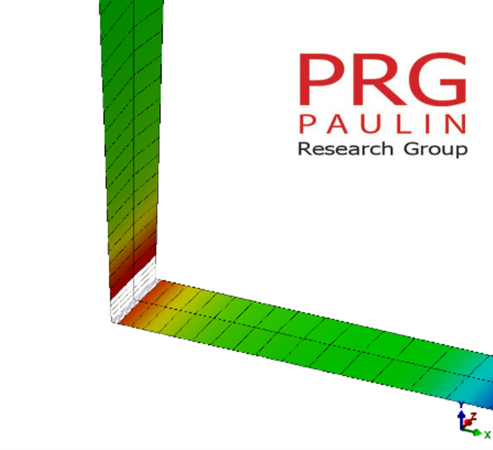
The figure below represents the solution data for a thermal ratcheting assessment using the MITCH elements. It’s important to note how in the first iterations there is a “shakedown” into a repeated plastic action. These solutions can be processed within minutes on standard PCs or desktops.
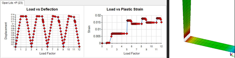
Figure 2: MSCN Solver Results in PRG Software
StressPLOT
For brick (3D) element and axisymmetric (2D) models, users can process stresses with the Stress Integration Method (in accordance with WRC 429) by specifying SCLs in StressPLOT.
This module of the software can take identified SCLs from the model and compute raw element stresses or linearized stresses, which users can use to plot and report local membrane and bending stresses.
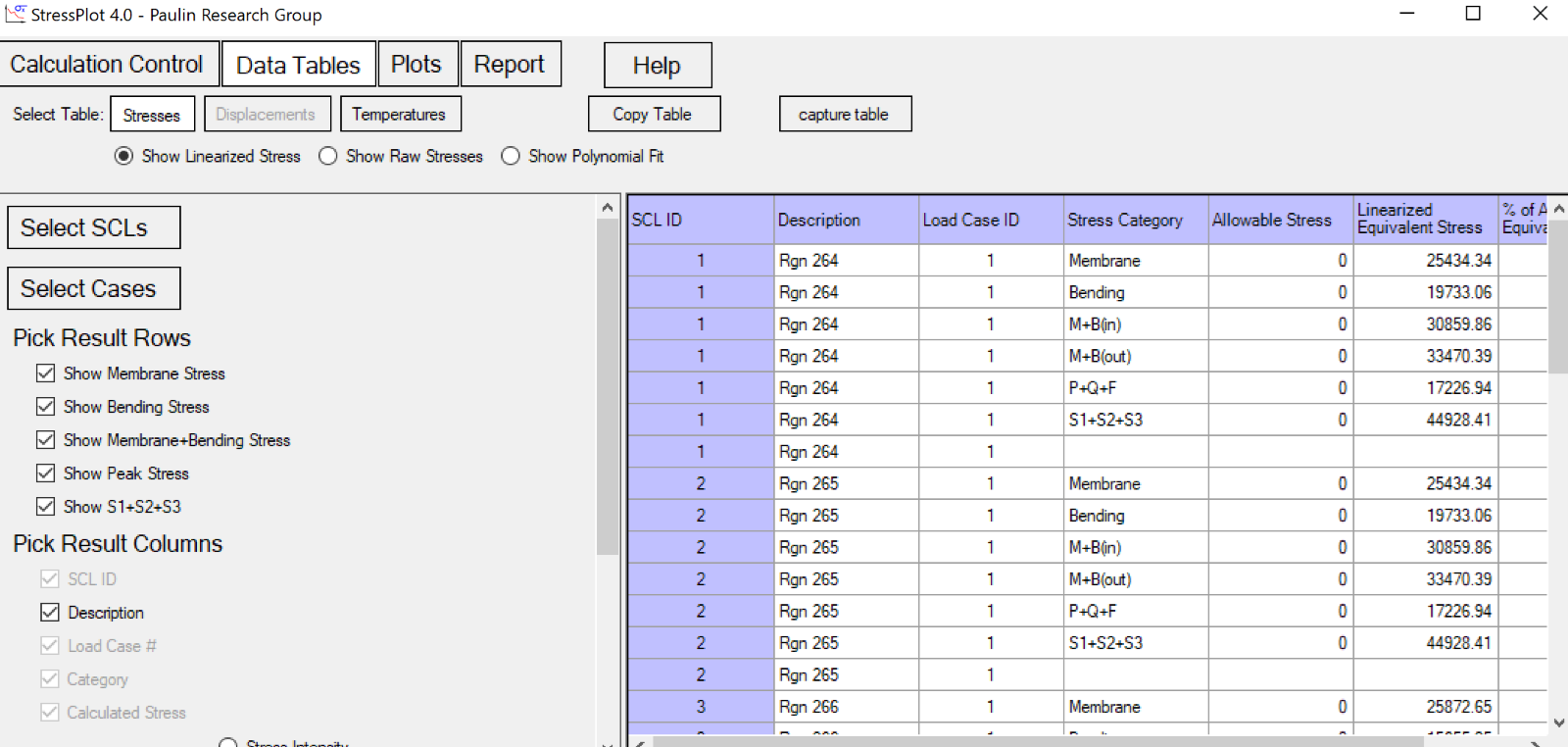
Figure 3: StressPLOT from PRG Software
Volumetric Model Analysis
For brick and axisymmetric element models, the user will more often need to adjust the mesh and ensure that stress classification lines are adequate, particularly in the circumferential plane for nozzle connections.
Like the shell model, the user can use the templates provided in the software to define the geometry, but unlike the shell geometries, the user may often need to manually adjust the volumetric meshes to achieve an adequate mesh. A number of PRG tools are available for users to confirm that elements are not deformed in shape and that SCLs are formed perpendicular to the surface of the shell so that membrane and bending stresses with respect to the cross-section can be properly evaluated.
Like with shell elements, PRG software automatically process membrane and bending stresses through SCLs across the model where they have been preselected, but users must confirm the locality of the stresses by plotting the SCL regions after the model has been run.
StressPLOT is used to augment the SCL evaluations if classification is needed in areas other than those selected by the software. NozzlePRO’s brick model templates and FEPipe’s branch connection templates have SCLs placed automatically at weld edges of repads, nozzles, tapers and shells. Maximum data is then displayed in the tabular output report (SCL results for brick models cannot be plotted).
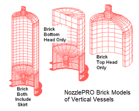
Figure 4: Brick Models of Vertical Vessels in PRG’s NozzlePRO
The stress linearization that a user performs in PRG software surrounds the following process:
- Define the SCL.
- Rotate the global tensors to local axes.
- Identify the integrations.
- Compute the principal components.
- Compute the stress intensity or equivalent stress.
There are also options to modify how the raw stresses are processed. In his research paper "Stress Classification Lines Straight Through Singularities,” for the ASME 2008 Pressure Vessel and Piping Conference, Arthurs Kalnins proposes zeroing the normal stress along the thickness direction and the surface shear stresses [1].
These tend to be artificial stresses when extracted from Gauss points and may not contribute to membrane and bending failure modes being modeled. Through-wall radial stresses are more significant in thicker geometries and where thermal gradients can exist.
Kalnins also points out that SCLs can be cut at sections where there are surface singularities, especially as the mesh is refined since the area associated with the singularity gets smaller and so the influence of the singularity is reduced [1].
In NozzlePRO, users can analyze volumetric models (see figures below) to further determine the stresses within SCLs.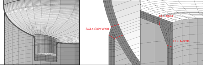
Figure 5: SCL Models in PRG’s NozzlePRO
Structural Stress Method
Alternatively, users can also use the structural stress method to process stresses from a shell model. In the codebook, Annex 5-A provides some guidance for how nodal force results can be used to compute the structural stress method on shell models, which is referenced for this method.
To compute these in PRG software, the model would have to be revised in the Drawing Tools, which allows the users to easily draw or add gussets, rings, clips and other attachments to an existing model. To model the weld according to Fig 5-A.9 and A.10 (displayed in the codebook), the user would map this in the Drawing Tools where the weld fillet is modeled with another set of elements. After making some quick modifications, the model must be submitted for normal processing (8-noded reduced integration elements). Then, the Drawing Tools processes nodal forces and computes stresses at the SCL that the user has specified.
The figure below shows alternative options for weld profiles to attempt to produce accurate stiffnesses in the vicinity of the penetration line. The use of an additional element in the vicinity whose thickness is equal to the fillet crotch thickness can be problematic since the axial stiffness and rotational stiffness of the penetration ring is not preserved. The model would be improved if the additional element was chosen to more accurately represent the more critical properties at the branch junction. The model below was constructed in a few minutes in the Drawing Tools.
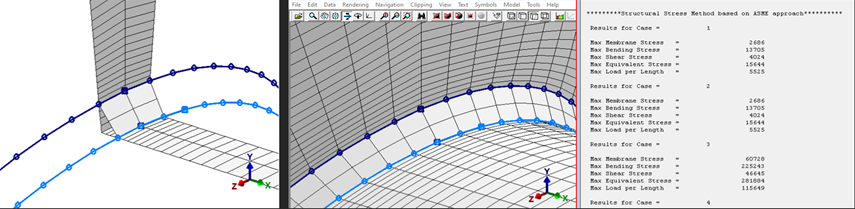
Figure 6: Overreach Elements in the Completed Model and Cross Section Total Loads in PRG Software
Structural stresses can be calculated from any drawn ring in a shell finite element geometry. Structural stresses are membrane and bending stresses that are computed using elemental forces and moments and not stresses extrapolated from the Gauss points. The structural stresses are generally considered “mesh independent,” but for shells or geometries where (DT)0.5 controls the inter-element load distribution, the solution will clearly be mesh dependent.
Solutions at structural drawn “rings” can be useful since the overall bending and membrane load/stress are available for the elements, but also for the drawn cross section. This feature can be used to draw a ring around the nozzle circumference to verify that the forces and moments are entered properly. The user can also see how the inter-elemental loads are distributed at cross sections due to supports, saddles and so on.
Who Can benefit from FEA Software?
For stress engineers, determining local discontinuity stresses for finite element models (FEMs) that are validated in compliance with ASME Section VIII Div 2, part 5 code is more easily accomplished with Paulin Research Group’s FEA software suite.
Additionally, our software helps users determine structured and unstructured meshing that is commonly used to represent a geometric domain by smaller discrete grid cells. As differences exist within each, the choice of applying structured or unstructured meshes to models depends greatly on the specific geometry and the time and resources available to analyze the model.
With PRG’s PVPTPro, NozzlePRO and FEPipe, there are benefits to using mesh modelers to rapidly produce verification results for pressure equipment. One of PRG’s lead engineers, Dr. Delin Wang (who is also responsible for creating the MCSN modeler), explains this clearly in his latest blog.
At PRG, our dedicated engineers are here to help make stress and piping engineers tasks more streamlined for better, faster and more compliant FEA models. To further see our software in action or how it can apply to your models, request a consult with our team today.
References
Kalnins, Arturs. “Stress Classification Lines Straight Through Singularities.” PVP2008-61746, pp. 317-326. ASME Pressure Vessel and Piping Digital Collections, ASME, 24 July 2009, https://asmedigitalcollection.asme.org/PVP/proceedings-abstract/PVP2008/48258/317/328910.