


In the latest edition of the ASME B31.3 code (2022 edition), there have been significant changes to the allowable stresses for expansion load cases (SA). Unlike previous editions, the 2022 edition introduces a new approach to calculating the Stress Range Factor (f) in Equation 1, which considers the cold and operating allowable stresses (Sc and Sh) for the specific material. The most notable change is the adjustment of the constant and exponent values in Equation 2, resulting in a slope change from 5 to 3. This modification has a positive impact on design conservativeness and enhances the fit of curves in piping intersections.
In the following blog, we discuss the research behind the B31 code change to the stress range factors, which was first theorized in the "Experimental Evaluation of the Markl Fatigue Methods and ASME Piping Stress Intensification Factors" paper coauthored1 by Tony Paulin and Chris Hinnant. These methods were further validated at Paulin Research Group's state-of-the-art laboratory in Houston, TX.
Stress Range Factor (f)
The 2022 edition of the ASME B31.3 code had a significant change to the allowable stresses for the expansion load cases (SA). As mentioned above, previous editions of the code used an allowable stress per Equaion 2 where the Stress Range Factor f was defined in Equation 1 and Sc and Sh represented the cold and operating allowable stresses for the given material. The 2022 edition changed the constant before the number of cycles (N) to 20 and the exponent from -0.2 to -0.333, which is equivalent to a slope change from 5 to 3 (see below):
f = 6N-0.2 <= fm (2020 B31.3) Equation 1
SA = f[1.25(Sc+Sh) – SL] Equation 2
f = 20N-0.333 <= fm (2022 B31.3) Equation 3
The Stress Range Factor (f ) is limited to a maximum value of 1.2 (fm) for materials with the tensile strength that's lower than or equal to 75 ksi (or kilo-pound per square inch), otherwise the maximum value is 1.0.
In the 2020 edition of the ASME B31.3 code, f equals 1.2, which corresponds to approximately 3,100 cycles (if the system cycles 200 times, it will still be designed for 3,100 cycles). In 2022 edition, the allowable stress is limited starting at approximately 4,600 cycles.
The limit on the Stress Range Factor f to 1.2 puts an upper limit on the allowable expansion stress range of around 2Sy when the yield stress governs the allowable. The new change is represented in the image below.
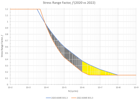
Figure 1: Stress Range Factor f Comparison in 2020 B31.3 and 2022 B31.3
Most notably, this change affects the high cycle stress ranges (N>50,000 cycles). The earlier B31.3 codes predicted non-conservative allowable cycles because the Markl slope was too shallow. The yellow shaded area represents high cycle ranges where Appendix W can be used, where different rules can apply. The B31.3 Appendix W rules refer to the more complicated ASME Section VIII, Div 2 Welded Fatigue curves, (since the B31 reference equation is the girth butt weld), but results in a slope and mean curve approximately the same as those shown in "Experimental Evaluation of the Markl Fatigue Methods and ASME Piping Stress Intensification Factors" and in Equation 3 above.
Accurately Determining Allowable Stress in High-Cycling Piping Systems
The slope change from 5 to 3 correctly lowered the allowable stress and removed the under-conservative nature of cycling piping systems that are exposed to cycles greater than 40,000 cycles.
The change to the Stress Range Factor was based on the "Experimental Evaluation of the Markl Fatigue Methods and ASME Piping Stress Intensification Factors" paper, which was validated with numerous fatigue tests performed at Paulin Research Group’s laboratory using cantilever beams and unreinforced fabricated intersections. The purpose was to determine a wider range of cycles to establish a better curve fit. The results conveyed that the slope of the curve differed from what A.R.C. Markl had originally predicted in his findings with fatigue testing.
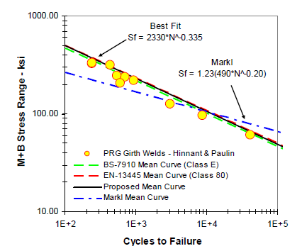
Figure 2: Mean Curve Comparisons Between PRG Girth Welds and Markl Curves
So, the best curve fit was determined and showed that the stress range curve fit should be Sf = 2330N-0.335 for the most accurate allowable stress predictions. These updated slopes further agree with the ASME Section VIII Division 2 Part 5 welded fatigue curve and most other welded fatigue curves used around the world.

PRG Piping & B31 Alignment
Paulin Research Group’s piping solutions like Konnect, PCLGold, and FEPipe implement the changes to the slope now published in the 2022 B31.3 edition of the code, where users can toggle between various pipe code editions for ASME B31.3 and ASME B31.1.
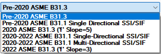
Figure 3: Code Options in PRG Software
Further, the user can easily see the comparison of allowable stresses by simply changing the B31.3 code year from 2022 to 2020.
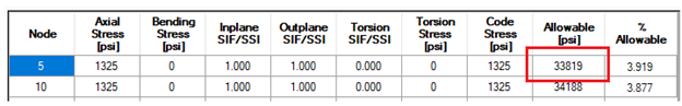
Figure 4: ASME 2020 Allowable Stress(SA)
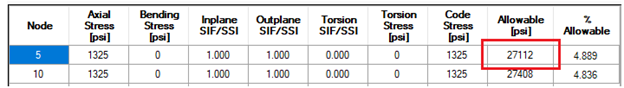
Figure 5: ASME 2022 Allowable Stress(SA)
The results below include the same geometry using the 2020 Stress Range Factor in Figure 3 and the 2022 Stress Range Factor in Figure 4. The number of cycles (N) in this model is 45,000.
f = 6N-0.2 = 6(45,000)-0.2 = 0.70390 Equation 4
SA = f[1.25(Sc+Sh) - SL] = 0.70390[1.25(20,000+20,000) – 1,954 psi] = 33,819 psi Equation 5
f = 20N-0.333 = 20(45,000)-0.333 = 0.5643 Equation 6
SA = f[1.25(Sc+Sh) - SL] = 0.56430[1.25(20,000+20,000) – 1,954 psi] = 27,112 psi Equation 7
Equations 4 and 5 show the allowable stress calculated using the 2020 Stress Range Factor for node 5. Equations 5 and 6 show the same calculation for using the 2022 Stress Range Factor.
The allowable stress in the 2020 code edition produced an under-conservative allowable stress for a number of cycles greater than 10,000 as represented in the gray area in Figure 1. The sustained stress (SL @ node 5 = 1,954 psi) to calculate the allowable per Equation 2 is the same for both code editions. This value is used in equations 5 and 7.
The calculation for node 10 can be performed in a similar manner, taking into account that the SL value may vary for the opposite side of the element. This further confirms the validity of the theories implemented by Tony Paulin and incorporated into PRG software, effectively reducing the allowable stress and eliminating the tendency for under-conservatism in cycling piping systems exposed to cycles exceeding 40,000 cycles.
Better Software, Safer Designs
The 2022 edition of the ASME B31.3 code has brought significant changes to the allowable stresses for expansion load cases, specifically in the calculation of the Stress Range Factor (f). These changes are based on extensive research and testing conducted at Paulin Research Group's laboratory. The new approach in the code has resulted in a more accurate and conservative design for piping intersections, particularly in high-cycle stress ranges. By implementing these changes, the industry can ensure the safety and reliability of piping systems.
To learn more about the research behind these code changes and how they can impact your piping design, we encourage you to connect with one of our consultants today.

References
1Hinnant, Chris and Paulin, Tony. “Experimental Evaluation of the Markl Fatigue Methods and ASME Piping Stress Intensification Factors.” ASME Digital Collection. New York, N.Y.