Buy Now Request a Consult

Technical Specs

FEPipe – 3D Piping & Pressure Vessel Design Software

FEA Complexity Made Simple


Download The Tech Specs

What Is FEPipe?


FEPipe is a template-based software solution specifically designed for the pressure vessel and piping (PV&P) industries. Based on the chosen template, FEPipe uses Finite Element Analysis (FEA) to comply with the ASME BPV Section VIII Division 2 guidelines. What separates FEPipe from general-purpose FEA software packages is its ability to rapidly construct PV&P geometries and produce ASME code compliance reports. Instead of generalized stress results, FEPipe displays results in terms of ASME compliance requirements.

FEPipe’s use of the parametric approach allows analysts to construct accurate models using only dimensional input. FEPipe automatically creates the model geometry, element mesh and boundary conditions based on a user’s dimensions of the applied loads with the ability to edit the model in the Drawing Tools.


Request a Consult

fepipe-hero-left

What does FEPipe include?

piping system_fepipe_weyer research


FEPipe Software Capabilities


FEPipe supports several model elements for rapid modeling and analysis, as well as an extensive element library that is easily searchable. The dropdowns below further outline this:

FEATools, is also included in FEPipe: FEATools transforms your piping (CAESAR II and PCL-Gold) by including upgraded branch connections (with the addition of rigid elements and restraints) to better simulate real-world displacement and forces. The FEA-based calculations provide the necessary k-factors, Stress Sustained Indexes (SSIs) and Sustained Intensification Factors (SIFs) that will be added to every branch connection.


How it Works


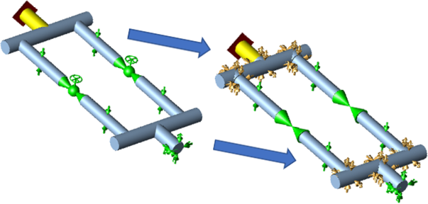
Step 1: In FEATools, run the piping model file (CAESAR II or PCL-Gold) to generate FEA-based SIFs, SSIs and k-factors.

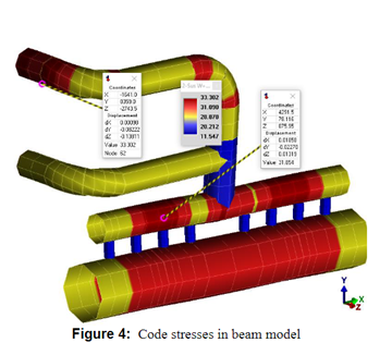
Step 2: Re-run the piping model file (CAESAR II or PCL-Gold) analysis to get more accurate stresses, loads, displacements and life cycles.

featools-hero

Features in FEPipe

FEPipe encompasses a variety of features and capabilities to automate and create efficiency for PV&P design and analysis.

Analysis

FEPipe supports a variety of analysis features for loads and load cases, nonlinear and linear analysis and more.

Design & Code Guidance on Advanced Geometries

PCL-Gold Pipe Stress Module

As a standalone module, PCL-Gold also connects to the latest version of FEATools. Click here to find out more.


Programs in FEPipe

Along with a variety of features, FEPipe utilizes several programs. A few include:

FEPipe-Image2

The Drawing Tools allows the user to add gussets, rings, clips and other attachments to an existing model.

FEPipe-Image3


FEPipe’s Fitness for Service program, API 579 Fitness for Service, allows for the direct entry of flaw or corrosion details. Users can enter the flaw dimensions directly (into the Critical Flaw Dimensions section), or the dimensions can be entered in a spreadsheet grid and the Critical Flaw Dimensions section will be automatically calculated. Users can also define the defect on the model graphically.

Users can add Local Thin Areas (LTA) and crack-like flaws using FEPipe, NozzlePRO or the Drawing Tools to perform API 579 or ASME FFS-1 Level 2 or 3 type analysis.

Additional Programs

Program Program Summary

NozzlePRO

NozzlePRO is a standalone solution that enables users to quickly and easily perform FEA of individual pressure vessel and piping components.

MatPRO

Is PRG’s own materials database that includes high temperature curves, allowable stress plots, NH reporting, creep-fatigue interaction diagrams, elastic-plastic stress strain curves and fatigue curves generated as a function of creep temperature.

FlangePro

FEA of flanged joints and other axisymmetric geometries. 3D, nonlinear finite element models of gaskets, bolts and flanges are used to calculate stresses, displacements and leakage in and around the flanged joint. Code evaluations of the joint are performed in accordance with ASME Section VIII-1 Appendix 2, ASME BFJ and EN13445 Annex G.

BoxPro

BoxPro analyzes header box nozzles for air-cooled heat exchangers. It also performs tube load analysis for multiple nozzle loads per ASME Section VIII-1 Appendix A per API 661. All nozzle loads are applied to the perforated tubesheet and analyzed per ASME 2004-Div. 2 Art 4-9.

FE107

FE107 replaces WRC 107 and 537 as a calculation tool that can be applied when WRC 107 or WRC 297 correlations or assumptions are limited. ASME Section VIII Division 2 allowables are printed along with flexibilities and allowable loads for forces, moments and pressure.

FESIF

Calculates SIFs and k-factors for standard B31 branch connection geometries.

FETee

Provides a FEA of contoured tees per user input, B16.9 or EN10253. EN10253 types A and B tees can be defined and thickness profiles determined and appropriate finite element models constructed. Elastic models to produce SIFs and k-factors are generated automatically, along with nonlinear calculations (with or without pressure) for SSIs and loads thru the branch or run. Users may locally thin tees, define the crotch radius and/or the thickness profile around the branch to run penetration line.

FEBend

Provides a FEA calculation of the local stress and SIFs, SSIs and k-factors for 90 degree elbows with and without supports. Supports include round stanchion as well as structural attachments.

PCL-Gold Pipe Stress

For piping systems in which there are well-known weaknesses in code approaches, PCL-Gold provides an alternative method for determining whether or not the weakness can cause a potential problem.

Pipe Shoe Design Wizard

Compares CAESAR II or PCL-Gold selected nodes’ restraint loads at shoe support locations with the allowable loads from a library of FEA shoe supports for every load case in the piping model. The comparison provides shoe design capabilities as well as validation that existing shoes are appropriately designed.

High Frequency

Acoustic Induced Vibration (AIV) calculation includes the prediction of sound pressure levels measurable away from the surface of the vessel. This tool
is used mainly to estimate strength of branch connections and elbows with trunnions when compared a straight pipe.

PRG performs high frequency vibration tests to confirm surface integration and prediction of damaging SPL.

Methods in IEC 60534-8-3 for gas flows are used to generate predicted SPL spectrum. Stresses in high-frequency modes are scaled to match defined spectrum responses and predict expected cycle lives.

Cumulative Damage

Performs fatigue analysis and cycle counting for piping systems that were built using CAESAR II or PCLGold. This tool can be used in the following situations:

• When cycles are outside limits

• When fatigue limits exist in a piping system

• When known fluid loading produces high cycle forces

• When cracks or local thin areas are present

• When multiple significant thermal and/or pressure cycles are present

• Elastic follow-up evaluation

BOS B31

The fluid-structure interaction using frequency domain analysis of piping systems is used to comply with the B31.3 loading requirements in Para. 301.5.

SIF / SSI / K (PRGik)

Compares SIFs and k-factors from B31 and other codes for branch connections and elbows. Hyper Degree of Freedom (HyperDOF) calculations can be performed for elbows with and without supports with refractory.

Flaw Detection

Predicts crack growth for given stress states in components to know when the crack will reach half wall and/or thru wall for leaks. This is a quick calculation based on observed crack growth in tested low carbon steel components.

MimOut Point Clouds

Plant scan data (point cloud data) processing is combined with 3D modeling utilities to compare computer model estimates of what is in the field to what physically exists. Both high and low-resolution editing is provided.

Drawing Tools

Available with all modules except AxiPRO, the Drawing Tools provide hundreds of small functions to modify, evaluate and document the model created.

Nonlinear Analysis

This capability computes burst pressures, sustained stress indices, twice elastic slope load levels, and a variety of load and unload conditions.

Fitness for Service

Perform level 1, level 2 and level 3 (through the Drawing Tools) Fitness for Service calculations. Local thin areas and cracks can be added into the model for level 3 calculations. API 579/ASME FFS-1 allows the use of ASME Section VIII Division 2 Part 5 for Elastic, Elastic-Perfectly Plastic and Elastic-Plastic FEA analysis.

FEATools

Transform your piping model (from CAESAR II and PCL-Gold) by including upgraded branch connections (with the addition of rigid elements and restraints) to better simulate real-world displacement and forces. The FEA-based calculations provide the necessary k-factors, SSIs and SIFs that will be added to every branch connection.

Why Choose FEPipe


FEPipe has been designed specifically for pipe designers and pressure vessel designers and fabricators to help prevent the common design, analysis and fatigue problems faced by engineers today. With the extensive features and knowledge behind FEPipe, users can feel confident designing their models for ASME code compliance with ease. With FEPipe, you can increase performance, shorten design cycles and reduce costs.

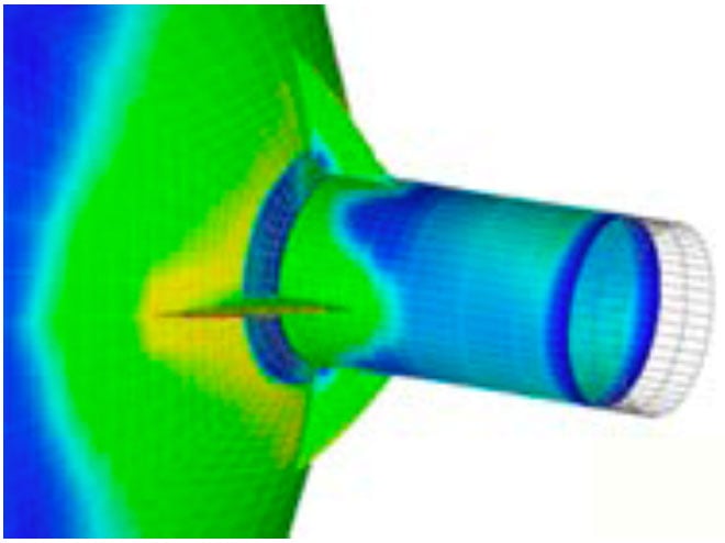
Additionally, Paulin Research Group develops their own research and methods and tests their theories in live simulations. Element formulations and related output have been compared against classical hand calculations and benchmarked against other general FEA software tools. Other research includes strain gauge measurements, burst tests, fatigue tests, cryogenic work, heat transfer experiments as well as acoustic vibration tests as shown below.


Request a Consult